
FAD Tools Frequently Asked Questions
Click on the questions below to show/hide the answers provided.
Licensing
All orders and payments must be submitted through our e-commerce platform powered by FastSpring. Payment is due in full in order to receive the requested licenses. Your order will trigger automatic emails with instructions for downloading and installing FAD Tools.
There are no discounts available at this point in time.
Your license subscriptions run in one-year terms based on the date of your order. They will renew upon the one year anniversary of the purchase. They can be renewed automatically or manually based on the options you select when purchasing the license. The payment notifications and renewal reminders will be sent to the email on file and payment can be made in the Subscription Portal. You may review and change this information at any time within the Subscription Portal.
Upgrades must be downloaded manually from our website in the Download Section of FAD website
FAD 4.0 is no longer supported by FAD Tools International and is not available for purchase. FAD 4.0 no longer meets ACI code for reinforcement design and does not contain the most up-to-date algorithms for foundation design. We recommend using the current version, FAD 5.1.18.
Maintenance subscription includes assistance installing the software and making it run on your system. It also includes verifying that the software functions correctly and fixing it in the event that it does not. Advanced questions regarding the capabilities of the software are included.
Maintenance subscription does not include answering basic questions that are addressed in the manual, engineering design support, interpretation of design, or training in the use of the software. Training is recommended. See below for training information.
Maintenance subscription questions should be addressed in email to support@fadtools.com. This allows for the question to be routed to the person most qualified to answer it.
Technical
The software will run on the 32 bit and x64 editions of Windows XP, Vista, Windows 7, Windows 8, Windows 10, and Windows 11.
I’m receiving the following messages when I try to open FAD Tools and the applicable database file. Is there a way to unlock the database file so I can save my changes?
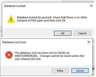
You can do any of the steps described below:
- 1- Update to the latest service pack for your FAD version (e.g. 5.2.1, 5.2.2 etc.). You can download the installer from our download webpage downloads.html . To check your version and service pack, click on Help/About and check the FAD Version and the Service Pack as shown in Figure 1 below:
- 2- Unlock the database following the steps described below (see Figures 2 and 3).
- (1) Open Access, click on open/Browse and select “All Files (*.*)” in the filter as shown in the figure below.
- (2) Open the *.fadt file, and click on the Table “DBFileLock”. Then select the rows indicating the owner and click “delete” as shown below and close the file. Be sure to click on the button “Enable Editing” if it shows on your screen.
- 3- Send us the input file *.fadt and we can unlock for you.

Figure 1. Checking Service Package (SP). Example of FAD 5.2.1 Service Pack 11.
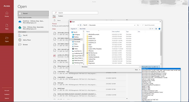
Figure 2. Opening the database in Access.
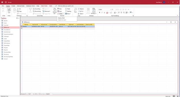
Figure 3. Opening “DBFileLock” Table
Yes you can.
The location of the license file in your computer or local network can be found as shown in Figure 1. For Cloud licenses, you can change this location any time after activation, but for PC license the location of the license file can be specified only during activation as shown in Figure 2. To change the location of the license file, you need to deactivate the license and activate back, in which case, you need to contact the FAD technical support team.
To change the location of the cloud license file, you would need to copy/paste the file to the new location, specify the new location as shown in Figure 1 and then restart FAD.
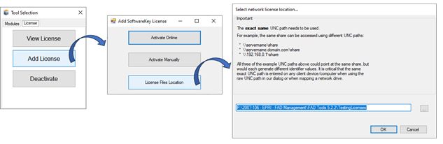
Figure 1. Finding out the location of the license file (*.lfx).
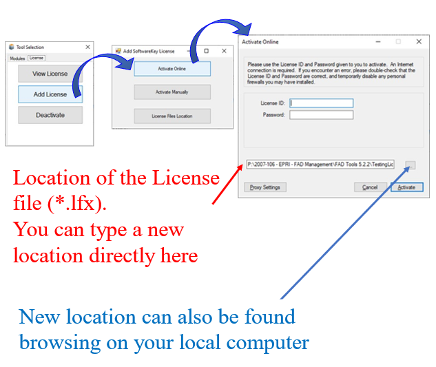
Figure 2. Location of the license file during activation.
FAD does not recognize the license after it is activated. The button for the license modules are disabled as shown in the example of Figure 1 below.
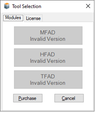
Figure 1. Example of FAD modules disabled.
In this case, perform the steps described in Figure 2. To find out the location of the license file on your computer, please follow the steps in Figure 3. Note that you can get the License File (#.lfx) from the license portal as shown in Figure 4 if you don’t find it on your computer.
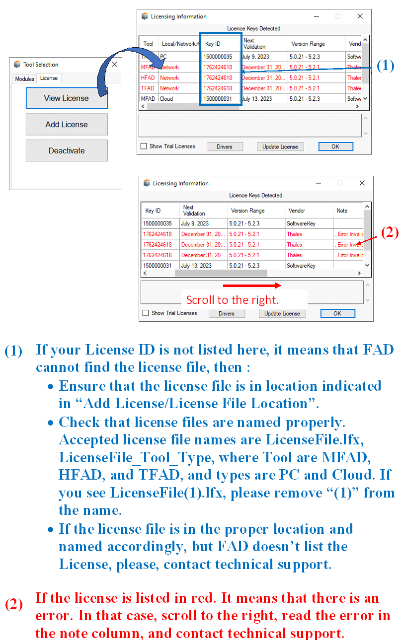
Figure 2. Troubleshooting installation of the FAD License.
Figure 3. Finding out the location of the license file (*.lfx).
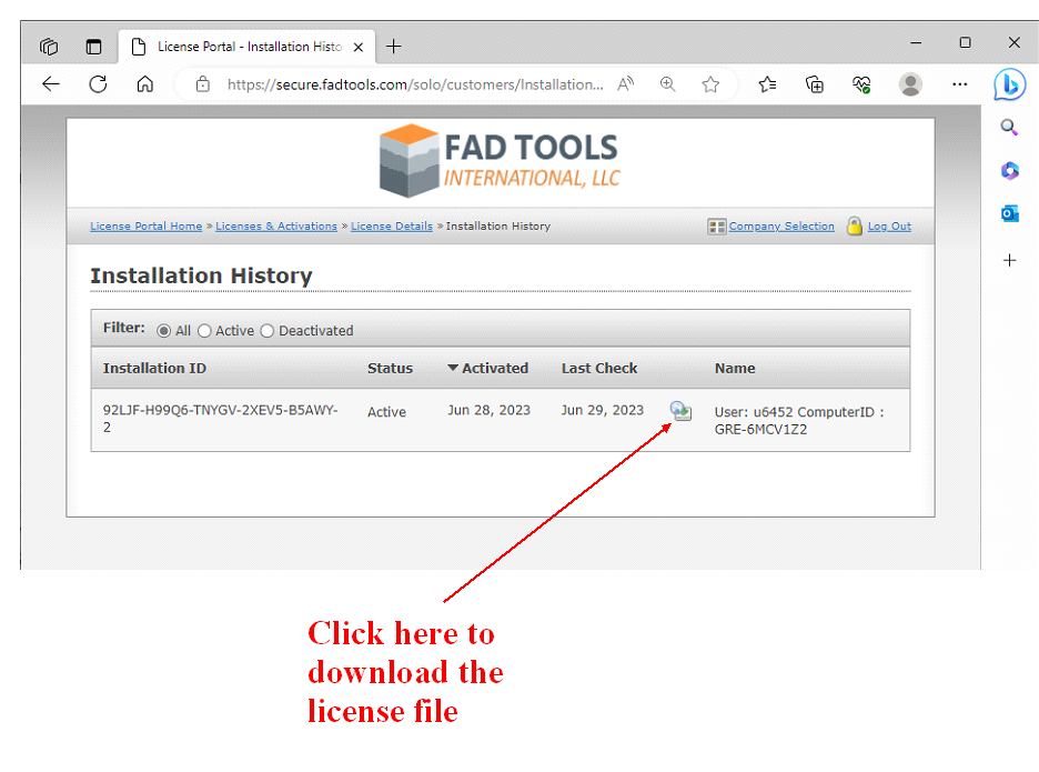
Figure 4. Downloading the License File.
FAD Tools 5.1 uses a database to store all program information. During installation, this database is installed in the FAD Tools folder on the local computer. The database can be moved to a network location to allow multiple users to access the same database.
To access your FAD 5.0 database with FAD 5.1, make a copy of your FAD 5.0 database and change the file extension to *.fadt. When prompted by FAD 5.1 to update the database, click ”yes”. Once the database has been updated it will no longer be able to be opened by FAD 5.0.
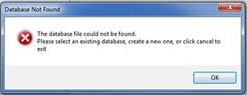
To move a database you can copy/cut and paste the database into the new location. As a heads up, every time FAD Tools opens it will try to open the most recently accessed database. If the most recently accessed database was moved/deleted, then you might see the following message appear when you open the program:
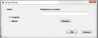
Following the steps below you can either create a new database or access an existing one. To switch databases once the program is open select “Options” and “Design Settings” and then “Browse”.
- Click on "Browse"
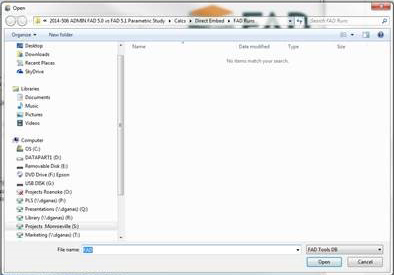
- The name and location of the database can be of your choosing. When you click “Open” it will ask if you want to create that database. Select yes. Or if there is an existing database you can search and select the database.
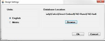
- The file path should appear under Database Location. Click “Ok” and the database should be ready to populate and the program ready to calculate.
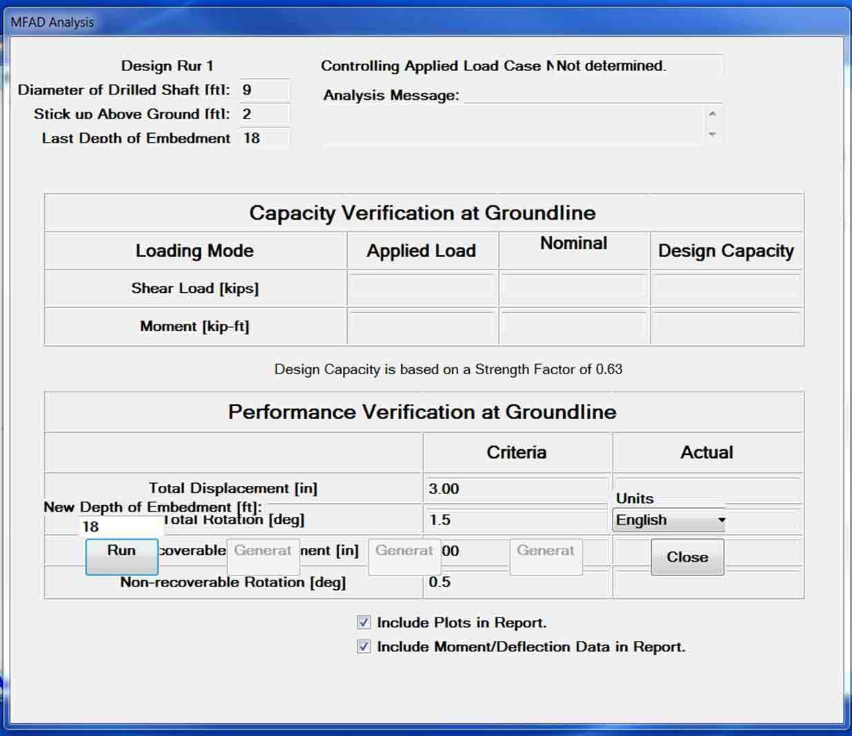
FAD Tools 5.1 is known to have a resolution problem causing buttons to move or disappear within certain pop-up windows.
As a temporary solution, it is recommended to change your display font size to Smaller- 100% (default) under the Windows Control Panel > Display.
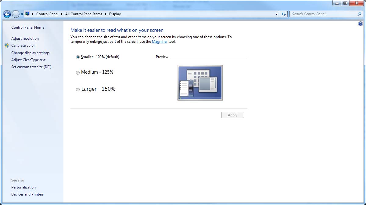
We are working to correct this error within the upcoming release of FAD Tools.
Engineering
Database files (with file extension .fadt) store project information including all the user input values into FAD and the results of the most recent foundation analyses. The database file is updated during the operation of FAD based on the user input values and analyses. The database file, therefore, should be stored in a location that the user has read/write access and should only be accessed by one user at a time. The default database file is stored where the FAD program was installed. The user is encouraged to create new database files and can copy files to create backups. New database files can be created from the file menu in FAD Version 5.1.20 or under the options menu in FAD Version 5.1.18.
Example Database files can be found under the Help menu within the FAD program or requested through maintenance subscription. Example results for these database files are also included. These examples are provided to verify that FAD is installed and functioning correctly.
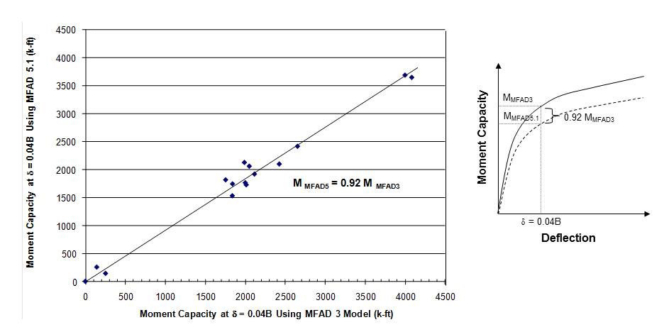
MFAD 5.1 includes updated algorithms to more accurately predict full-scale foundation load test results performed during the original development of the model. The end result of this re-calibration is a slightly softer deformation response than seen in earlier MFAD versions, where the same soils and load parameters result in an increased deflection on the order of 8% to 9% with the newer version (Kandaris 2011 presentation for EPRI).
EPRI Full Scale Foundation Tests Predicted Moment Capacity at δ = 0.04B
The software has been designed for ease of use. It is up to the engineer of record, however, to verify the model, the geotechnical properties, loads, and performance parameters are appropriate for the given design case. The User's Guide contains information on the assumptions and limitations of the FAD program. If you have questions on the use of the software please contact support. If you are interested in further training, please contact us.
Training classes are designed for the specific needs of our clients. Please contact us for a training quote. Direct questions about the program can be answered through our support team. Please contact us at anytime by email at support@fadtools.com. We also offer a Users Group meeting periodically to cover aspects of the FAD program for all active subscribers to the maintenance program.
The FAD 5.0 (and newer) software is based the calibration of full-scale foundation tests using a Reliability Based Design (RBD) methodology. As such, there is no “safety factor” per allowable stress design methodology as the program assumes the use of RBD. Please see section A.3 on Reliability Based Design in the FAD User’s Guide.
MFAD 5.0 (and newer) have a built in resistance factor of 0.63 which is used to calculate the design shear and moment capacity at the groundline.
Versions of FAD 5.0 (and newer) also report the Nominal (ultimate) design shear and moment capacity (i.e., prior to multiplication by the 0.63 resistance factor) which could be used to evaluate foundation designs with a factor of safety. However, we caution that FAD was created using the RBD methodology.
We are aware that some users use MFAD, HFAD, and/or TFAD for the design of A-frame structure. The FAD program was not calibrated for A-frame structures, however, depending on the load combination and dimensions the results of a FAD analysis may be an appropriate model. Ultimately it is up to the user to verify the applicability of the software for their design conditions. Please see the User Guide for details on the different FAD modules.
Note that only the MFAD program has been calibrated for load-performance equilibrium. HFAD and TFAD do not consider the performance (rotation or deflection) related to moment-uplift/compression interaction or torsion. Implicit in the HFAD and TFAD modules is the assumption that there is only minimal vertical displacement where bearing capacity is not a controlling factor in design. The user is encouraged to perform supplemental analyses outside of the program to verify bearing capacity when site specific conditions vary from program assumptions (e.g. negative skin friction, shrink-swell, and collapsible soils).
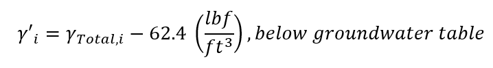
The ground water table is set in the geotechnical parameters data tab by the function “Depth To Water” (see figure below) and is used to internally calculate the effective unit weight when a layer is below the ground water table (see equations below). By default, the FAD program sets the “Depth To Water” to zero, assuming the groundwater table starts at the ground line and all layers below are saturated. The user should enter the design depth to saturated layer using the “Depth To Water”. The “Total Unit Weight” below this depth should saturated.
For layers located below the ground water table, the following equation is used in the program:
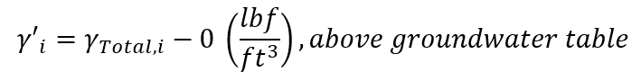
Above the groundwater table, the user entered “Total Unit Weight” is directly used in the calculations as follows:
For conditions where the design “Depth To Water” is at a considerable depth, the program will function properly if the user entered depth is below the last layers’ “Depth to Bottom of Layer (ft)”. We are aware that some users:
- Apply default values of 100 ft to model unsaturated soil profiles even though their soil profiles only extend to 30 ft.
- Set the “Depth To Water” to a considerable depth and then enter effective unit weight values into the “Total Unit Weight” for both the subsurface and backfill (annulus) properties. The program will calculate. This calculation does not include the buoyant unit weight of concrete in the base moment and base shear springs.
- Use the moist (bulk) unit weight for soils above the “Depth To Water”, but these soils typically have low a degree of saturation and are based on field and laboratory testing. Note, below the “Depth To Water” the “Total Unit Weight” values must be greater than the unit weight of water for the program to calculate properly.
Ultimately, it is up to the engineer of record to verify the geotechnical parameters used within the FAD program.
Please be aware that a project may appear to be duplicated when you open up FAD. This display error can occur when there was a communication delay when pulling the project name and the project data from the database file. Do not delete the duplicate Project as this will delete all data.
The program will function normally with the duplicate Project title. Meanwhile, reopening the program will remove the duplicate. We are working with our programmer to prevent this error.
We recommend saving the database file (extension FADT) frequently. The current location of the database file can be found under the FILE tab, then selecting the OPEN. You can copy and move the database file within Windows explorer.
The FAD Tools 5.0 (and newer) software was based upon the calibration of full-scale foundation tests using a Reliability Based Design (RBD) methodology. As FAD Tools uses an RBD design there is no “safety factor” per Allowable Stress Design methodology (ASD). Please see section A.3 on Reliability Based Design in the FAD User’s Gu
MFAD 5.0 (and newer) has a built in resistance factor of 0.63 which is used to calculate the design shear and moment capacity at the groundline. Resistance factors for HFAD and TFAD can be found in the FAD Users Guide. Please see tables A.42 and A.43.
Versions of FAD Tools 5.0 (and newer) also report the Nominal (ultimate) design shear and moment capacity (i.e., prior to multiplication by the resistance factor) which could be used to evaluate foundation designs with a factor of safety. We caution that FAD Tools was created using the RBD methodology and assumptions may not be appropriate for ASD design.
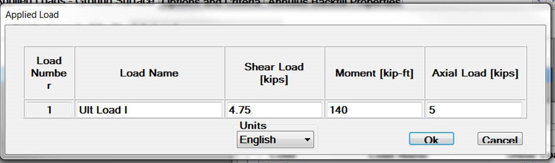
There are no limits to loads the user can enter in the MFAD program, although there are warning messages that indicate the loads are outside the calibration of the model. These warnings are based in part on the limits of full scale testing, the limits of the short-rigid shaft model, and the industry standard at the time of full scale testing. The following warnings are provided to the user:
- Axial loads input range of 0 - 250 kips
- Moment input range of 0 - 30,000 kip-ft
- Shear loads input range of 0 - 300 kips
We are aware that customers use MFAD for design of foundations with larger loads. We would caution that the use of the strength factor and model calibration for reliability based design in MFAD may not be appropriate for all loading conditions. Ultimately, it is up to the engineer of record to determine that the applied loads are appropriate for the MFAD model.
The MFAD foundation model was designed for laterally loaded foundations, as such the controlling forces are expected to be shear and moment loads. The MFAD foundation model exhibits rigid body motion under lateral loading (no curvature of the shaft), with a point of rotation near the lower one‐third of the foundation embedment depth. Per the EPRI 2197 report, a foundation is considered rigid where:
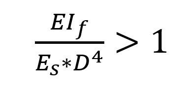
where EIf is the effective flexural stiffness the foundation (drilled shaft, direct embed), Es is the modulus of the subsurface (pressuremeter modulus) and D is the depth of embedment.
See the updated user guide for additional information and references to the original full scale testing.
There are no limits to reactions users can enter in the FAD program, although there are warning messages that indicate the reactions are outside the calibration of the model. These warnings are based in part on the limits of full scale testing, the limits of the short-rigid shaft model, and the industry standard at the time of full scale testing. The following warnings are provided to the user for MFAD:
- Axial input range of 0-250 kips
- Moment input range of 0-30,000 kip-ft
- Shear loads input range of 0-300 kips
We are aware that customers use FAD for design of foundations with larger reactions. We would caution that the use of the strength factor and model calibration for reliability-based design in FAD, may not be appropriate for all loading conditions. Ultimately, it is up to the engineer of record to determine that the applied reactions are appropriate for the MFAD model and their design conditions.
The FAD foundation model is designed for laterally loaded foundations, as such the controlling reactions are expected to be shear and moment loads in MFAD. The MFAD foundation model exhibits rigid body motion under lateral loading (no curvature of the shaft), with a point of rotation near the lower one- third of the foundation embedment depth. Per the EPRI 2197 Vol. 2 report Equation 4-7, as Rk approaches infinity pier behavior approaches that of a rigid body, following:
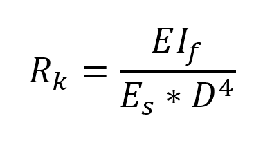
where EIf is the effective flexural stiffness the foundation (drilled shaft or direct embed), Es is the modulus of the subsurface (pressure meter modulus) and D is the depth of embedment.
In terms of reactions, the foundation behavior should be verified to behave as a short-rigid shaft under the expected loading conditions. Please note that factors of an axially load foundations such as negative skin friction, settlement, and collapsible soil layers are not accounted for in FAD and other models/calculations may be more appropriate for your given condition.
Within FAD, for all foundations with stickup (reveal), the entered applied reactions at top of shaft are converted to applied reactions at groundline. The applied moment will increase proportionally to the applied shear at top of shaft by the length of the stick up while the applied shear and applied axial loads remain the same. All calculations of design capacity and nominal capacity are at groundline.
The table headers in the HFAD Report currently have the wrong table headers. The values in all tables in the HFAD Report are for the groundline condition but the titles mistakenly identify them as top of shaft reactions. Our programmers are currently working on an update to FAD 5.2.1 to fix the titles.
Within FAD, for all foundations with stickup (reveal), the entered applied reactions at top of shaft are converted to aplied reactions at groundline. The applied moment will increase proportionally to the applied shear at top of shaft by the length of the stick up while the applied shear and applied axial loads remain the same. All calulations of design capacity and nominal capacity are at groundline.
There are various reasons why near surface properties may require a discount (reduction in properties), however the FAD model was not designed to evaluate low-bound properties or zero strength soil layers. The FAD model and its calibration to Reliability Based Design is based on characteristic (nominal) soil properties. We would caution that applying zero strength or near zero strength properties may cause the program to function outside the model parameters and the calibration may not be appropriate. In some cases, use of zero strength properties may produce "infinity" results or other unexpected results. See the FAD 5.2.1 User Guide for additional information.
Please not the program will round data entry values that are equal to or less than 0.01 to zero.
Additionally, direct embedment foundations have multiple modes of failure that are considered - within the backfill material, within the native subsurface material, and interaction between backfill and native material. If the subsurface properties are set to zero or nearly zero, the backfill response to load may not be consistent with expected failure conditions. Please also note that the backfill properties were based on testing of full-strength concrete, various densities of aggregate, and various densities of native fill materials. Use of other backfill materials may be outside the scope of the program.
The following options may be an appropriate way of modeling soil discounts within the FAD modules:
- Reducing the strength properties of the upper soil layer by a percentage within the expected design range
- Modeling the subsurface without the upper soil layer and modifying reactions and displacement for the change in groundline
- Modeling the soil layer with full strength properties, with the assumption that the strength reduction factor accounts for possible variation in subsurface conditions.
Please not that each of these options have inherent assumptions and associated risk, and that there are some conditions that may not warrant a discount in near surface soils. Please work with your geotechnical engineer to determine the appropriate subsurface parameters for the given design condition.
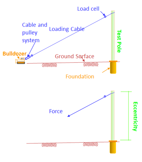
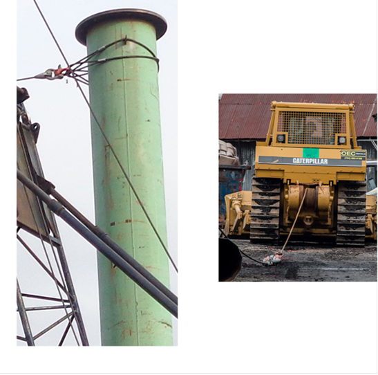
The “eccentricity” is defined within FAD as the ratio between applied moment (Mapp) and applied shear (Vapp) plus the stick up as shown in the equation below and Figure 1. FAD calculates the capacity and the moment-displacement curve for a constant eccentricity and vertical load. These assumptions approximate the conditions in the full-scale load tests used to calibrate FAD (see Figure 2 below). Thus, the eccentricity can be considered as the height of the test pole or the distance between the cable/pole connection and the base plate. Also, if one accepts that the inclination of the cable is low enough so that the vertical load variation is negligible then this test can be considered as a pole loaded with an incremental lateral load applied at a height equal to FAD’s eccentricity.
eccentricity=Applied Momment at groundlineApplied Shear force at groundline / Applied Momment on top of shaftApplied Shear force on top of shaft+stick up
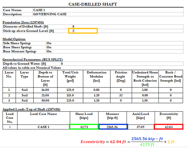
Figure 1. Example of the eccentricity calculation.
Legacy Hardware Keys
To troubleshoot the installation of FAD with “ContainerNotFound” error:
- Find where the Network key is located, and get the IP address of this computer. The Network key is a red dongle.
- Check if the Network key is visible from the computer where you installed FAD. There are different ways to check this:
- Type http://localhost:1947/_int_/devices.html in the web browser where you installed FAD. The key should appear as shown in see Figure 1.
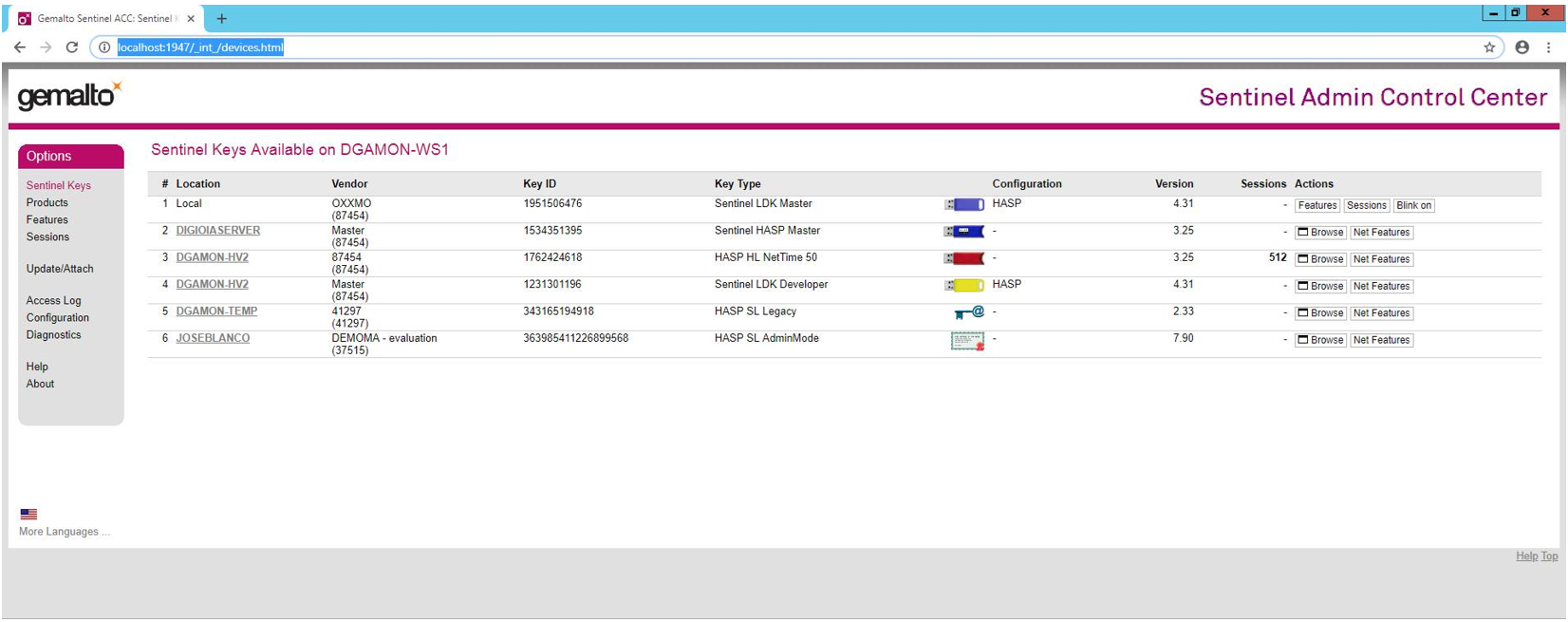
- The FAD Tools key can be identified by either the vendor number (87454) or the key ID supplied by the FAD Tools representative.
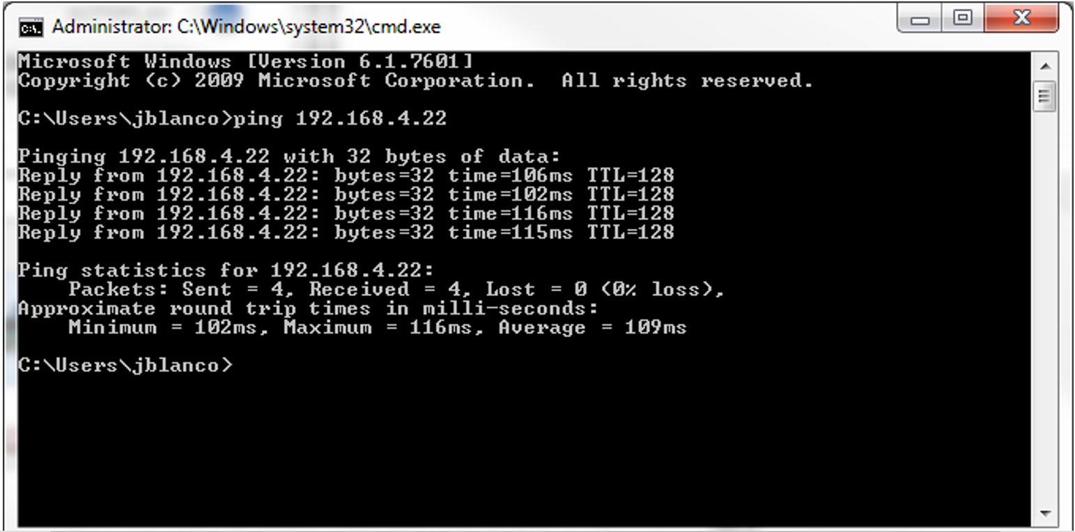
- Type “ping ‘IP address where the network key is located’” from cmd line of the computer where you are installing FAD. If the computer is visible, then you see a reply as shown in Figure 2.
- If Method 1 doesn’t show the key on the computer where you installed the key, but Method 2 does get a reply, then try the following steps:
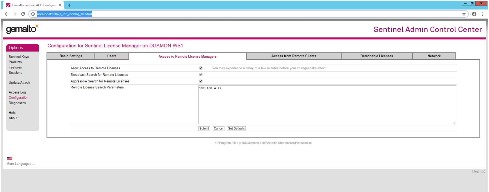
- Type http://localhost:1947/_int_/config_to.html in the computer where you are installing FAD and click on “Access to Remote License Managers”. Then type in the IP address of the computer where the Network key is located and check “Aggressive Search for Remote Licenses”. See Figure 3 for an example.
- If this doesn’t work, then check that Sentinel driver is installed in the computer where the network key is plugged in.
- One way to do this is to type http://localhost:1947/_int_/config_to.html in the computer with the network key. If you don’t see a webpage similar to Figure 3, then you need to install the driver in this computer as well. To do this, please, download the HASP Sentinel Driver installer from http://fadtools.com/html/downloads.html and install it in this computer with the network key is located.
- If none of the two previous steps work, even though you can see the computer where the network is connected using method 2, then contact us again because we need to reopen this ticket with Gemalto.
- If method 2 is not getting a reply from the computer where the network key is plugged into (e.g. Figure 2), then this is a problem in your network. The IT person should resolve this. We can provide ideas but no one knows the local network better than an internal IT person. You can still try to do steps 1 and 2 of the previous steps and see if this helps.